Product Description
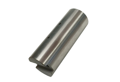
Includes Cold End Assembly, Coupler with set screw, (2) O-Rings and a Sump seal. Every cold end comes with all new soft goods and inspected or replaced major components.
IMPORTANT NOTICE
If the returned cold end assembly is not received back within 14 days of receipt your credit card will be charged $2,635.73.
Additional charges may be applied for wear beyond normal scope of exchange policy.
Please return the material, with a copy of the enclosed Packing Slip, to:
CryoVation
9b Mary Way
Hainesport, NJ 08036
Please properly package the returning material to avoid freight damage charges.
If you should have any questions please contact us at any of the following:
NJ Phone: 609-914-4792
E-mail: info@cryovation.com
INSTRUCTIONS
REMOVAL OF COLD END
The cold end may be repaired while still connected to the skid (minor repair) but should be removed and taken to a clean area to reduce chance of contamination.
1. Ascertain that the liquid vessel vapor return and liquid supply valves to the pump are closed and pressure in the sump is vented.
2. Remove vent return and liquid supply lines to the sump.
3. Disconnect the discharge line into the surge chamber.
4. Remove the belt guard attachment screws and lift belt guard off.
5. Remove the pump anchor plate bolts and tilt the entire drive/cold end assembly back to the horizontal position. This provides for easier access at a more convenient working height. At this point the entire assembly could be removed from the skid and transported to a more favorable working area.
6. Remove sump by removing the sump attachment bolts (Item 40). Gloves and safety glasses should be worn when removing sump in case residual liquid is still present in the sump.
7. To disconnect the cold end body loosen the Pushrod retainer nut (Item 32), the discharge line retainer nut (Item 41), remove the two discharge line attachment bolts (Item 31) and remove the cold end body attachment bolts (Item 42).
8. The entire cold end body assembly may now be removed for disassembly.
SETTING THE PISTON CLEARANCE
After any re-assembly of either the drive end or cold end assemblies the piston "End" clearance must be reset. The desired clearance between the piston and the valve body should be .020 (.50MM).
1. With coupler (Item 36) installed on the Pushrod (Item 22) and all shims removed, insert a piece of wood between the coupler and drive end Crosshead. Rotate the large pulley until the Crosshead pushes the piston to its "bottom" most position.
2. Remove the wood spacer and continue to rotate pulley until the Crosshead is at bottom most position.
3. Insert a feeler gauge, between the coupler and Crosshead, at the slot in the Crosshead. Gap should be between .040" to 070" (1.016 - 1.778 MM).
4. Determine the proper thickness of shims to install as follows (assume measured gap was .055" (1.397 MM).
.055" Measured Gap
-.020" Desired Gap (with shims)
.035 " Shims required
5. Shims are laminated to allow for make-up of exact thickness desired.
6. Insert shims between coupler and Crosshead and recheck final clearance (.020" 50MM).
7. Tighten the two bolts (Item 39) refer to parts list cold end. Rotate large pulley to make certain that piston does not bottom or "tap" against valve body.
RE- INSTALLATION OF COLD END ASSEMBLY
1. Clean inner recess of Cold End Intermediate (Item 43) where Cold End Assembly will be installed.
2. Insert O-Ring (Item 10) into recess.
3. Insert new O-Ring (Item 12) into groove on end of Internal Discharge Tube (Item 35).
4. Install Cold End Assembly into Intermediate Assembly and bolt together (Item 42).
5. Bolt Discharge Tube to the Retainer Plate (Item 9) with two bolts (Items 31 & 5).
6. ScrewbrassLocknutontoPushrod(Item22),machinedendfirst,andscrew down to bottom of threads.
7. Screw Coupler (Item 36) onto Pushrod until Coupler bottoms. Tighten both items together.
8. Insert nylon tipped Setscrew into Coupler and tighten. Insert second set screw to lock against the first.
9. Tighten brass Locknut against the bottom of the Coupler.


